| # | Problem Description | Code | |
|---|---|---|---|
| 1 | 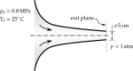 Flow rate. Pressure and temperature at nozzle exit. |
-- | -- |
| 2 |  Normal shock in nozzle, Supersonic flow at the exit plane, Minimum reservoir pressure for choking. |
-- | -- |
| 3 |  Maximum back-pressure to choke the nozzle, Normal shock in the nozzle, Back-pressure for perfectly expanded nozzle, Supersonic flow at the nozzle exit plane. |
-- | -- |
| 4 |  Throat and exit areas of the nozzle, Design back-pressure and temperature, Lowest back-pressure with no supersonic flow, Back-pressure with no shock waves. |
-- | -- |
| 5 |  Maximum back-pressure for choking, Back-pressures for shock in the nozzle, Design back-pressure, Back-pressures for supersonic flow at nozzle exit. |
-- | -- |
| 6 |  Flow rate under design conditions, Exit area of the nozzle, Design back-pressure and the temperature, Lowest back-pressure for which there is only subsonic flow, Back-pressure for normal shock wave on the exit plane, Back-pressure for no shock waves in the nozzle, Back-pressures for oblique shock waves, Back-pressures for expansion waves, Back-pressures at which a normal shock wave in divergent section. |
-- | -- |
| 7 |  Variable area diffuser. |
-- | -- |
| 8 |  Exit area of the nozzle, Mass flow rate at design conditions, Back-pressure when normal shock wave at exit, Back-pressures for expansion waves. |
-- | -- |
| 9 |  Rocket nozzle thrust at sea level versus space. |
-- | -- |
| 10 |  Throat area, exit area and exit velocity. |
-- | -- |
| 11 |  Mass flow rate through CD passage, Mach number at the minimum area section, Velocity and pressure at the exit section. |
-- | -- |
| 12 |  Nozzle throat area, Mach numbers before and after the shock, Nozzle area where the shock occurs, Nozzle area at exit, Density at exit of the nozzle. |
-- | -- |
| 13 |  Mach number and the temperature at nozzle exit, Nozzle area where the normal shock wave occurs. |
-- | -- |
| 14 |  Pressure, temperature, and Mach number at the nozzle exit. |
-- | -- |
| 15 | 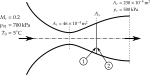 Nozzle area where the shock occurs, Mach number and pressure just before and just after the shock wave. |
-- | -- |
| 16 |  Inlet and exit Mach numbers, Increase in entropy, Area where the shock occurs, Stagnation pressure at the exit. |
-- | -- |
| 17 |  Exit area, Exit temperature, Exit Mach number, Area where the shock wave occurs, Pressure ratio across the shock. |
-- | -- |
| 18 |  Pressure in the reservoir for normal shock at nozzle exit. |
-- | -- |
| 19 |  Nozzle area at which the normal shock wave is located, Increase in entropy across the shock, Back-pressure when shock wave is located at nozzle exit. |
-- | -- |
| 20 |  Nozzle throat area, Nozzle exit area, Temperatures upstream and downstream of the shock wave, Change in entropy through the nozzle. |
-- | -- |
| 21 |  Mass flow rate at design conditions, Exit pressure when normal shock wave occurs in the divergent section. |
-- | -- |
| 22 |  Mach number at exit of the nozzle. |
-- | -- |
| 23 |  Minimum supply stagnation pressure for choking the nozzle, Mass flow rate through the nozzle, Supply stagnation pressure when normal shock wave occurs in the divergent portion. |
-- | -- |
| 24 |  Mach numbers on each side of this shock wave, Back-pressure required to maintain the shock at a location. |
-- | -- |
| 25 |  Throat areas of the nozzle and diffuser. |
-- | -- |
| 26 |  Mach number, Stagnation temperature and pressure, Mass flow rate through the nozzle, Exit area, pressure, and temperature. |
-- | -- |
| 27 |  Mass flow rate of carbon dioxide using venturimeter. |
-- | -- |
| 28 |  Large rocket engine designed to propel a satellite launcher, Throat and exit diameters of the nozzle. |
-- | -- |
| 29 |  Mach number, temperature, and velocity of the air at the discharge. |
-- | -- |
| 30 |  A small jet aircraft designed to cruise at Mach 1.5, Ideal area ratio for this diffuser, Mach number to which the aircraft must be taken to swallow the normal shock wave. |
-- | -- |
| 31 |  Fixed supersonic convergent-divergent diffuser, Mach number to swallow the shock during startup. |
-- | -- |
| 32 |  Variable-area diffuser, Percentage reduction in diffuser throat area. |
-- | -- |
| 33 |  Diffuser with a variable area ratio, Throat area at cruise / throat area at given Mach. |
-- | -- |
| 34 |  Percentage increase in throat area. |
-- | -- |
| 35 |  Wind tunnel test section with a variable area diffuser, Idea diffuser throat area / Starting throat area. |
-- | -- |
| 36 |  Rate of air discharge from a tank. |
-- | -- |
| 37 |  Transonic wind tunnel testing. |
-- | -- |
| 38 |  Pressures and Mach numbers at given cross-sectional area. |
-- | -- |
| 39 |  Moving piston, Air velocity at exit, Piston velocity, Flow rate of discharged air. |
-- | -- |
| 40 |  Pressure in the second reservoir. |
-- | -- |
| 41 |  Angle of flow at discharge. |
-- | -- |
| 42 | 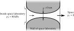 Meteorite punching hole in the skin of an orbiting space laboratory. |
-- | -- |
| 43 |  Jet engine is running on a test bed. |
-- | -- |
| 44 |  Back-pressures for constant mass flow rate. |
-- | -- |
| 45 |  Nozzle area at which the shock wave occurs. |
-- | -- |
| 46 |  Exit area of the nozzle, Mass flow rate at design conditions, Back-pressure when normal shock wave on the exit plane, Back-pressures when normal shock wave in the nozzle, Back-pressures when oblique shock waves will occur, Back-pressures when expansion waves will occur. |
-- | -- |
| 47 |  Mach number and flow direction just downstream of oblique shock waves. |
-- | -- |
| 48 |  Flow direction just downstream of expansion waves, Effect of expansion waves on thrust. |
-- | -- |